
Local Grill Monitoring Setup
System Overview: The Local Grill Monitoring Setup provides a 100% self-hosted, cloud-free telemetry and historical graphing pipeline for the FireBoard 2 (FBX2-GJ8RC3JRD) 6-probe grill thermometer. An internal Seeed Studio XIAO ESP32-C3 (switched on/off automatically by an IRLB8721PBF N-Channel MOSFET driven from the FireBoard's [Pin 35: TXD0] pad) reads all probe channels over Bluetooth Low Energy GATT and posts live updates over Wi-Fi to https://grill.drheck.dev (http://10.0.0.3:8088/api/ingest).
1. Bench Wiring & Flashing Guide (Seeed Studio XIAO ESP32-C3 + IRLB8721PBF)
1.1 Bill of Materials (BOM)
- Microcontroller: Seeed Studio XIAO ESP32-C3 ($21\text{ mm} \times 17.5\text{ mm}$, built-in Li-Ion battery pads on underside + external
U.FLantenna socket). - External Antenna: Included Seeed
U.FL(IPEX) 2.4 GHz flexible dipole sticker antenna (snap onto the XIAO'sANTsocket before powering on; adhere inside the plastic FireBoard shell away from the metal Li-Ion pouch cell). - Power Switch MOSFET:
IRLB8721PBFTO-220 Logic-Level N-Channel MOSFET ($V_{\text{GS(th)}} = 1.35\text{ V–}2.35\text{ V}$, $R_{\text{DS(on)}} \approx 0.013\text{ }\Omega$ at $V_{\text{GS}} = 3.3\text{ V}$). - Resistors (
1/4W 1%Metal Film):1x 100kΩ(Required): Gate pull-down resistor between MOSFET Pin 1 (Gate) and Pin 3 (Source / GND) so the MOSFET snaps 100% shut ($0.000\text{ mA}$ standby drain) the instant the FireBoard turns off.2x 100kΩ(Optional — for Battery % Telemetry): 50/50 voltage divider (BAT+$\longrightarrow$XIAO A0$\longrightarrow$XIAO GND).
1.2 Step-by-Step Pin Connections
MOSFET Pin Orientation (IRLB8721PBF): Hold the MOSFET with the black printed label facing you and the metal heatsink tab facing away (legs pointing down). From left to right, the 3 legs are:
• Pin 1 (Left Leg): Gate (G) — Trigger input ($3.3\text{ V}$ ON / $0.0\text{ V}$ OFF)
• Pin 2 (Middle Leg): Drain (D) — Switched ground going to XIAO BAT-
• Pin 3 (Right Leg): Source (S) — True ground going to FireBoard Battery - (GND)
Required Connections (4 Wires + 1x 100kΩ Resistor)
- FireBoard Battery
+(Red) $\longrightarrow$ XIAO undersideBAT+pad. - FireBoard Battery
-(GND) $\longrightarrow$ MOSFET Pin 3 (Right Leg,Source). - MOSFET Pin 2 (Middle Leg,
Drain) $\longrightarrow$ XIAO undersideBAT-pad. - FireBoard 6-pin header top-left pad (
[Pin 35: TXD0]) $\longrightarrow$ MOSFET Pin 1 (Left Leg,Gate), AND solder1x 100kΩresistor between MOSFET Pin 1 (Gate) and MOSFET Pin 3 (Source / GND).
Optional Battery % Sense Divider (2x 100kΩ Resistors on Pin A0)
- Solder
1x 100kΩresistor (R1) from FireBoard Battery+(BAT+) to XIAO PinA0(top-left pin next to the USB-C port,GPIO2). - Solder
1x 100kΩresistor (R2) from XIAO PinA0to XIAOGND(orBAT-). - (If omitted, the firmware automatically detects $<1.5\text{ V}$ on
A0, disables the software low-battery sleep cutoff, and reports100%battery to the dashboard).
1.3 Complete Wiring Schematic
  FIREBOARD 2 MAIN PCB / BATTERY                   IRLB8721PBF MOSFET              SEEED XIAO ESP32-C3
  ==============================                   (Label Facing You)              ===================

  1S Li-Ion Battery (+) [3.7V-4.2V] ---------------------------------------------> Underside [BAT+] Pad
                                                       |
                                                    [100kΩ] (Optional R1)
                                                       |
                                                       +-------------------------> Top-Left Pin [A0 / GPIO2]
                                                       |
                                                    [100kΩ] (Optional R2)
                                                       |
                                                       v
  6-Pin Header [35 TXD0] (3.3V ON) ------------> Pin 1 [Gate (G) - Left]
                                                       |
                                                    [100kΩ] (Pull-Down to GND)
                                                       |
  1S Li-Ion Battery (-) / [GND] ---------------> Pin 3 [Source (S) - Right]

                                                 Pin 2 [Drain (D) - Middle] -----> Underside [BAT-] Pad
Why Power Connects to the Underside BAT+ / BAT- Pads (Not the Top 5V Pin): On the Seeed Studio XIAO ESP32-C3, the top 5V (VBUS) pin passes through a protection Schottky diode ($\Delta V_{\text{diode}} \approx 0.34\text{ V}$) before feeding the XC6206P332MR $3.3\text{ V}$ LDO ($\Delta V_{\text{drop}} \approx 0.25\text{ V}$), requiring at least $3.85\text{ V}$ on 5V before the $3.3\text{ V}$ rail sags. Soldering to the underside BAT+ pad bypasses the Schottky diode and feeds the LDO directly ($V_{\text{min}} = 3.30\text{ V} + 0.25\text{ V} = 3.55\text{ V}$), running cleanly across the entire $3.5\text{ V–}4.2\text{ V}$ discharge curve of the 1S Li-Ion cell.
$$V_{\text{ADC}} = V_{\text{BAT}} \times \frac{R_2}{R_1 + R_2} = \frac{V_{\text{BAT}}}{2.0}, \qquad I_{\text{divider}} = \frac{4.2\text{ V}}{200\text{ k}\Omega} = 21\text{ }\mu\text{A}$$
1.4 Building, Flashing & Bench Testing (PlatformIO)
- Snap the
U.FLantenna onto the XIAO ESP32-C3 before powering on. - Copy
include/secrets.example.htoinclude/secrets.hin~/git/grill-syncand set your 2.4 GHz Wi-Fi credentials:#define WIFI_SSID "Your_2.4GHz_WiFi_SSID" #define WIFI_PASSWORD "Your_WiFi_Password" - Compile, flash over USB-C, and open the live serial monitor (
115200baud):$ pio run -t upload -t monitor - Turn on the FireBoard 2 nearby with a probe plugged into Channel 1. Within 5 seconds, the serial console outputs:
=== FireBoard 2 BLE -> Wi-Fi Sync (XIAO ESP32-C3) ===
[WiFi] Connected, IP: 10.0.0.x
[BLE] Found FireBoard (94:54:c5:f7:1c:fa, RSSI -42 dBm)
[BLE] Connected to FireBoard 2
[BLE] Subscribed and sent 0x01 start command
[BLE] Ch 1: 72.5 F
[HTTP] POST http://10.0.0.3:8088/api/ingest -> 200
2. FireBoard 2 Hardware Forensics & PCB Pinout Reference
2.1 Internal ESP32-WROVER-E Photograph & Pin Labels
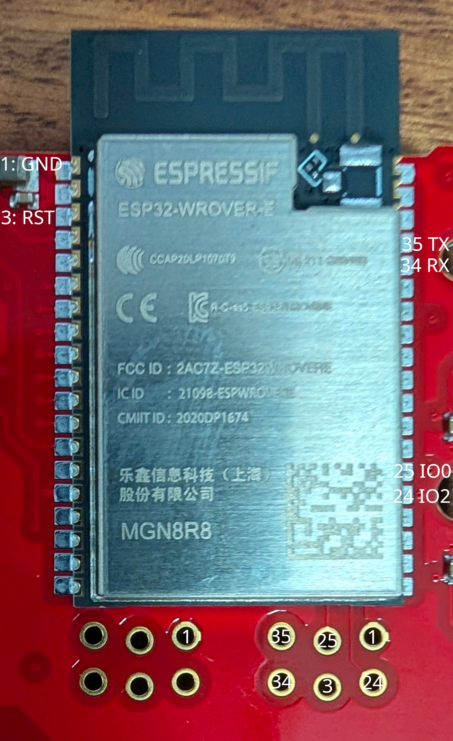 Figure 1: FireBoard 2 internal ESP32-WROVER-E (MGN8R8) module and unpopulated 6-pin 1.27mm UART bootloader header with verified pin numbers.
2.2 Unpopulated 6-Pin 1.27mm (0.050") Debug Header Pinout
Located immediately below the ESP32-WROVER-E module on the main PCB. All pads were verified by continuity against the castellated ESP32-WROVER-E pins:
      TOP ROW (Closer to ESP32 bottom edge)
   +----------------+----------------+----------------+
   |  [Pin 35] *    |  [Pin 25]      |  [GND]         |
   |  UART0 TXD0    |  GPIO0 (BOOT)  |  Ground        |
   |  (Right #23)   |  (Right #14)   |  (Shield/1/15) |
   +----------------+----------------+----------------+
   |  [Pin 34]      |  [Pin 3]       |  [Pin 24]      |
   |  UART0 RXD0    |  EN / RST      |  GPIO2 (Strap) |
   |  (Right #22)   |  (Left #3)     |  (Right #13)   |
   +----------------+----------------+----------------+
      BOTTOM ROW (Closer to PCB edge)

   * [Pin 35: TXD0] (top-left pad) outputs 3.30V when FireBoard is ON
     and 0.00V when FireBoard is OFF — wire this pad to MOSFET Pin 1 (Gate).
| Header Pad | ESP32 Module Pin | Function | Voltage (FireBoard ON) | Voltage (FireBoard OFF) | Notes |
|---|---|---|---|---|---|
[35 TXD0] |
Pin 35 (Right #23) |
GPIO1 / U0TXD |
$3.30\text{ V}$ (Idle High) | $0.00\text{ V}$ | Used as the $3.3\text{ V}$ ON/OFF trigger for MOSFET Pin 1 (Gate) |
[34 RXD0] |
Pin 34 (Right #22) |
GPIO3 / U0RXD |
$3.30\text{ V}$ | $0.00\text{ V}$ | UART0 receive input |
[25 IO0] |
Pin 25 (Right #14) |
GPIO0 (Boot Strap) |
$3.30\text{ V}$ | $0.00\text{ V}$ | Hold at $0\text{ V}$ (GND) while pulsing [3 RST] to enter UART Download Mode |
[3 RST] |
Pin 3 (Left #3) |
CHIP_PU (EN / RST) |
$3.30\text{ V}$ | $0.00\text{ V}$ | Active-low hardware reset ($0\text{ V}$ resets ESP32) |
[24 IO2] |
Pin 24 (Right #13) |
GPIO2 (Boot Strap) |
$0.00\text{ V}$ | $0.00\text{ V}$ | Must be low/floating to enter serial bootloader |
[GND] |
Pins 1, 15, 38, 39 | Common Ground | $0.00\text{ V}$ | $0.00\text{ V}$ | Connected to ESP32 RF shield can and battery negative (-) |
Additional Module Reference Pad: Left #2 (Pin 2: 3V3) carries the regulated $3.30\text{ V}$ rail when the FireBoard is powered on and drops to $0.00\text{ V}$ when powered off.
2.3 Recovered Device & Silicon Identity (esptool / espefuse)
| Property | Value | Notes |
|---|---|---|
| Device Hostname / Serial | FBX2-GJ8RC3JRD |
FireBoard 2 6-Channel Thermometer |
| MCU Module | ESP32-WROVER-E (MGN8R8) |
8 MB Quad-SPI Flash (a1:4017) + 8 MB PSRAM |
| Silicon Die Revision | ESP32-D0WD-V3 (revision v3.1) |
Dual-Core Xtensa LX6 @ $240\text{ MHz}$, $40\text{ MHz}$ crystal |
Wi-Fi STA MAC (Base) |
94:54:c5:f7:1c:f8 |
Reserved as 10.0.0.71 in ~/git/router_config/dhcpd.conf on danknasty |
Wi-Fi SoftAP MAC (Base + 1) |
94:54:c5:f7:1c:f9 |
Used only during initial mobile app Wi-Fi setup |
Bluetooth LE MAC (Base + 2) |
94:54:c5:f7:1c:fa |
Always active whenever the FireBoard 2 is powered on |
| Battery Pack | 1S Li-Ion Pouch Cell ($3.7\text{ V}$ nominal, $4.20\text{ V}$ full) |
Charged via USB-C 5V charging circuit on main board |
2.4 Why the Stock Firmware Could Not Be Redirected or Replaced
- Closed Local Network Surface: Full 65,535-port TCP/UDP
nmapscans and packet captures against10.0.0.71confirmed the stock firmware listens on zero local ports and initiates outbound TLS 1.2 connections exclusively to FireBoard Cloud (fireboard.io) with strict CA certificate verification andSNIchecks. - Locked Factory Silicon (
eFuses): Interrogation over the 6-pin UART bootloader header proved all hardware security eFuses are permanently burned:- Flash Encryption (
FLASH_CRYPT_CNT = 127/0b1111111): All 7 bits burned and write-protected; plaintext flashing renders the chip unbootable. - UART Crypto Disabled (
DISABLE_DL_ENCRYPT = True,DISABLE_DL_DECRYPT = True): The ROM bootloader is physically barred from encrypting new images or decrypting flash over UART. - Secure Boot v1 (
ABS_DONE_0 = True): Only images signed with FireBoard's private key (BLOCK2, read/write protected) are booted. - Silent UART Console (
MTDOStrapped Low +ESP_LOG_NONE): Zero application log bytes are emitted onUART0during normal boot.
- Flash Encryption (
Click to expand full ESP32-D0WD-V3 Security eFuse Register Dump (espefuse summary)
FLASH_CRYPT_CNT        (BLOCK0) = 127 R/- (0b1111111)  [Flash encryption permanently enabled; odd bit count = 7; Write-Protected]
FLASH_CRYPT_CONFIG     (BLOCK0) = 15  R/W (0xf)        [Full AES flash encryption tweak configuration]
ABS_DONE_0             (BLOCK0) = True R/W             [Secure Boot V1 permanently enforced on boot]
DISABLE_DL_ENCRYPT     (BLOCK0) = True R/W             [UART bootloader flash encryption disabled]
DISABLE_DL_DECRYPT     (BLOCK0) = True R/W             [UART bootloader flash decryption disabled]
DISABLE_DL_CACHE       (BLOCK0) = True R/W             [UART bootloader MMU flash cache disabled]
JTAG_DISABLE           (BLOCK0) = True R/W             [Hardware JTAG debugging permanently disabled]
CONSOLE_DEBUG_DISABLE  (BLOCK0) = True R/W             [ROM BASIC fallback console disabled]
BLOCK1 (Flash Key)              = ?? ?? ... -/-        [256-bit AES Flash Encryption Key: Read & Write Protected]
BLOCK2 (Secure Boot Key)        = ?? ?? ... -/-        [256-bit Secure Boot Key: Read & Write Protected]
3. FireBoard 2 BLE GATT Protocol Reference
Zero Cloud Dependency: The FireBoard 2 BLE GATT server remains active regardless of Wi-Fi state, including after an on-device Factory Reset that wipes Wi-Fi credentials.
| GATT Attribute | UUID / Value | Properties | Description |
|---|---|---|---|
FIREBOARD_DATA_CHAR_UUID |
c2f780ec-45e1-452b-a879-327e3140d1f1 |
Notify |
Streams UTF-8 JSON temperature packets every 3–5s per active probe channel |
FIREBOARD_CONTROL_CHAR_UUID |
c2f780ec-45e1-452b-a879-327e3140d1e8 |
Write |
Writing single byte 0x01 starts the notification stream on d1f1 |
FIREBOARD_START_STREAM_BYTE |
0x01 (b'\x01') |
1 Byte |
Must be written after enabling notifications (CCCD) on d1f1 |
BLE Handshake & Notification Payload Format
- Scan & Connect: Connect to BLE MAC
94:54:c5:f7:1c:fa(or any device matching prefix94:54:c5:f7:1c:/ nameFBX). No pairing PIN or bond is required. - Subscribe: Enable GATT notifications on
c2f780ec-45e1-452b-a879-327e3140d1f1. - Start Stream: Write
0x01(1 byte, with response) toc2f780ec-45e1-452b-a879-327e3140d1e8. - Parse JSON Notifications: The FireBoard immediately begins emitting UTF-8 JSON notifications for each connected thermistor probe (
channel1through6):{ "channel": 1, "temp": 225.4, "degreetype": 2, "date": "2026-09-28T20:30:00Z" }channel: Probe port number (1..6).temp: Floating-point temperature (nullor<= 0when unplugged).degreetype:2= Fahrenheit (°F),1= Celsius (°C).
4. Firmware Repository (~/git/grill-sync) & Magic Constants (include/config.h)
All hardware, BLE protocol, ADC resistor, and network constants are isolated in include/config.h (with Wi-Fi credentials in gitignored include/secrets.h).
Repository Layout
platformio.ini— PlatformIO configuration targetingseeed_xiao_esp32c3(huge_app.csv3.1 MB partition table,NimBLE-Arduino,ArduinoJson).include/config.h— Central configuration file containing all network URLs, MAC addresses, BLE GATT UUIDs, start byte (0x01), resistor divider values, and voltage thresholds.include/secrets.example.h/include/secrets.h— Local Wi-Fi credentials (WIFI_SSID,WIFI_PASSWORD) and optional local overrides.src/main.cpp— Non-blocking BLE GATT client, JSON parser, battery monitor, and HTTP POST transmitter.
Complete Reference of Constants in include/config.h
| Constant | Default Value | Purpose & When to Change |
|---|---|---|
INGEST_URL |
"http://10.0.0.3:8088/api/ingest" |
Target HTTP POST URL on host ul (10.0.0.3 ports 8088 and 8000). Change if ul's LAN IP ever changes, or set to "https://grill.drheck.dev/api/ingest". |
HTTP_POST_INTERVAL_MS |
5000UL (5s) |
How frequently the XIAO posts temperature snapshots to ul. |
WIFI_CONNECT_TIMEOUT_MS |
10000UL (10s) |
Maximum time spent waiting for Wi-Fi association per attempt. |
FIREBOARD_DEVICE_ID |
"FBX2-GJ8RC3JRD" |
Device ID reported in JSON payloads to ul. |
FIREBOARD_WIFI_MAC |
"94:54:c5:f7:1c:f8" |
Base / Wi-Fi MAC of the FireBoard 2 (assigned static IP 10.0.0.71 in ~/git/router_config/dhcpd.conf on danknasty). |
FIREBOARD_BLE_MAC |
"94:54:c5:f7:1c:fa" |
Bluetooth LE MAC of the FireBoard 2 (Base MAC + 2). Change if pairing with a replacement FireBoard unit. |
FIREBOARD_MAC_PREFIX |
"94:54:c5:f7:1c:" |
OUI/prefix matched during BLE scanning. |
FIREBOARD_LOCK_TO_MAC |
0 |
Set to 1 to only connect to FIREBOARD_BLE_MAC, or 0 to also connect to any nearby device advertising "FBX" / "FireBoard". |
FIREBOARD_DATA_CHAR_UUID |
"c2f780ec-45e1-452b-a879-327e3140d1f1" |
FireBoard 2 BLE GATT Notify characteristic that outputs JSON temperature readings. |
FIREBOARD_CONTROL_CHAR_UUID |
"c2f780ec-45e1-452b-a879-327e3140d1e8" |
FireBoard 2 BLE GATT Write characteristic that starts the stream when 0x01 is written. |
FIREBOARD_START_STREAM_BYTE |
0x01 |
Magic wake byte written to FIREBOARD_CONTROL_CHAR_UUID upon BLE connect. |
FIREBOARD_MAX_CHANNELS |
6 |
Maximum probe channel index (Channels 1..6). |
FIREBOARD_PROBE_STALE_MS |
30000UL (30s) |
Time without a BLE notification before a channel is considered unplugged. |
PIN_BATTERY_ADC |
A0 (GPIO2) |
XIAO pin reading the midpoint of the battery voltage divider. |
VOLTAGE_DIVIDER_R1_OHMS |
100000.0f ($100\text{ k}\Omega$) |
Upper resistor from BAT+ to A0. |
VOLTAGE_DIVIDER_R2_OHMS |
100000.0f ($100\text{ k}\Omega$) |
Lower resistor from A0 to GND. |
ADC_CALIBRATION_FACTOR |
1.000f |
Multiplier to fine-tune the ADC reading against a multimeter measurement. |
BATTERY_FULL_VOLTS |
4.15f |
Voltage mapped to 100% battery on the dashboard. |
BATTERY_EMPTY_VOLTS |
3.30f |
Voltage mapped to 0% battery on the dashboard. |
BATTERY_LOW_CUTOFF_VOLTS |
3.25f |
Software safety threshold ($3.25\text{ V}$) that puts the XIAO into deep sleep if the MOSFET switch is not present. |
5. Dashboard Infrastructure Reference on Host ul (https://grill.drheck.dev)
| Component | Path / Address | Details |
|---|---|---|
| Public URL (SSO Protected) | https://grill.drheck.dev (https://fireboard.drheck.dev) | Protected by Authentik ForwardAuth (Grill Monitor (FireBoard 2) application tile in user portal) |
| Unauthenticated Ingest API | http://10.0.0.3:8088/api/ingest / http://10.0.0.3:8000/api/ingest / https://grill.drheck.dev/api/ingest |
Accepts POST JSON ({"device_id": "FBX2-GJ8RC3JRD", "battery": 95, "rssi": -42, "probes": {"1": 225.4, "2": 165.2}}) |
| Docker Compose & App Source | /data/docker/grill/docker-compose.yml, /data/docker/grill/app.py |
Docker container grill running FastAPI + SQLite (WAL mode) + Chart.js live/historical multi-channel dashboard |
| Persistent SQLite Database | /data/docker/grill/data/grill.db |
Stores historical temperature series (1h, 3h, 6h, 12h, 24h, 48h views) |
| Dedicated Docker ULA IPv6 | fd77:7777:5010:0:1337:f1ac:d00d:fb02 (Port 8000) |
Bound on eth77 (10.0.0.3:8088 and 10.0.0.3:8000 mapped on IPv4 LAN for the XIAO ESP32-C3) |
| DNS Configuration | ~/git/router_config/unbound.conf & update_dns.py |
Local Unbound (10.0.0.100 / fd77:7777:5010::1337:f1ac:d00d:aaaa) on danknasty + public deSEC IPv6 GUA sync |
| Nginx Site Config | /etc/nginx/sites-available/grill |
Proxies / with Authentik ForwardAuth and /api/ingest with auth_request off |
| Backup & Restore Scripts | ~/git/backups/ul/scripts/grill_backup, grill_restore |
shellcheck-verified backups with par2 create -r10 parity archives in /data/backups/services/grill/ |