
Local Grill Monitoring Setup
System Overview: The Local Grill Monitoring Setup provides a 100% self-hosted, cloud-free telemetry and historical graphing pipeline for the FireBoard 2 (FBX2-GJ8RC3JRD) 6-probe grill thermometer. The FireBoard 2 itself has no IP address and no Wi-Fi connection. Instead, an internal Seeed Studio XIAO ESP32-C3 bridge (hostname fireboardctl.drheck.dev, static DHCP IP 10.0.0.71, Wi-Fi MAC 80:f1:b2:51:49:20), switched on/on and off automaticallyin hardware by an IRLB8721PBF N-Channel MOSFET driven directly from the FireBoard's [Pin 35: TXD0] pad, reads all probe channels over Bluetooth Low Energy GATT (94:54:c5:f7:1c:fa) and posts live updates over Wi-Fi to https://grill.drheck.dev (http://10.0.0.3:8088/api/ingest).
1. BenchHardware Wiring & Flashing Guide (Seeed Studio XIAO ESP32-C3 + IRLB8721PBF) MOSFET)
1.1 BillParts of Materials (BOM)Used
- Microcontroller (
fireboardctl.drheck.dev): Seeed Studio XIAO ESP32-C3 ($21\text{ mm} \times 17.5\text{ mm}$, Wi-Fi STA MAC80:f1:b2:51:49:20, static DHCP IP10.0.0.71, built-in Li-Ion battery pads on underside + externalU.FLantenna socket). - External Antenna: Included Seeed
U.FL(IPEX) 2.4 GHz flexible dipole sticker antenna (snap onto the XIAO'sANTsocket before powering on; adhere inside the plastic FireBoard shell away from the metal Li-Ion pouch cell). - Hardware Power Switch MOSFET:
IRLB8721PBFTO-220 Logic-Level N-Channel MOSFET ($V_{\text{GS(th)}} = 1.35\text{ V–}2.35\text{ V}$, $R_{\text{DS(on)}} \approx 0.013\text{ }\Omega$ at $V_{\text{GS}} = 3.3\text{ V}$). Resistors (1/4W 1%Metal Film):1x 100kΩ(Required): Gate pull-down resistor between MOSFETPin 1 (Gate)andPin 3 (Source / GND)so the MOSFET snaps 100% shut ($0.000\text{ mA}$ standby drain) the instant the FireBoard turns off.
2x 100kΩBAT+XIAO A0XIAO GND1.2 Step-by-Step Pin Connections (4 Wires Total)
MOSFET Pin Orientation (IRLB8721PBF): Hold the MOSFET with the black printed label facing you and the metal heatsink tab facing away (legs pointing down). From left to right, the 3 legs are:
• Pin 1 (Left Leg): Gate (G) — Trigger input ($3.3\text{ V}$ ON / $0.0\text{ V}$ OFF)
• Pin 2 (Middle Leg): Drain (D) — Switched ground going to XIAO BAT-
• Pin 3 (Right Leg): Source (S) — True ground going to FireBoard Battery - (GND)
Required Connections (4 Wires + 1x 100kΩ Resistor)
- Wire 1 (
BAT+Power): FireBoard Battery+(Red) $\longrightarrow$ XIAO undersideBAT+pad. - Wire 2 (
SourceGround): FireBoard Battery-(Black /GND) $\longrightarrow$ MOSFET Pin 3 (Right Leg,Source). - Wire 3 (
DrainSwitched Ground): MOSFET Pin 2 (Middle Leg,Drain) $\longrightarrow$ XIAO undersideBAT-pad. - Wire 4 (
Gate3.3V Trigger): FireBoard 6-pin header top-left pad ([Pin 35: TXD0]) $\longrightarrow$ MOSFET Pin 1 (Left Leg,Gate). - When the FireBoard 2 is turned ON,
AND[Pinoutputs $3.30\text{ V}$, turning thesolder35: TXD0]1x 100kΩIRLB8721PBFresistorbetweenMOSFETMOSFET Pin 1 (Gate)ON and connecting the XIAO'sBAT-pad to ground so the XIAO boots immediately.
[Pin 335: (Source / GND).Optional Battery % Sense Divider (2x 100kΩTXD0]Resistors on Pin A0)
1x 100kΩR1+BAT+A0IRLB8721PBF GPIO21x 100kΩR2A0GNDBAT-#define ENABLE_BATTERY_ADC 1include/config.hENABLE_BATTERY_ADC0A01.3 Complete Wiring4-Wire Schematic
  FIREBOARD 2 MAIN PCB / BATTERY                   IRLB8721PBF MOSFET              SEEED XIAO ESP32-C3
  ==============================                   (Label Facing You)              ===================

  1S Li-Ion Battery (+) [3.7V-4.2V] ---------------------------------------------> Underside [BAT+] Pad

  |
                                                    [100kΩ] (Optional R1)
                                                       |
                                                       +-------------------------> Top-Left Pin [A0 / GPIO2]
                                                       |
                                                    [100kΩ] (Optional R2)
                                                       |
                                                       v
  6-Pin Header [35 TXD0] (3.3V ON)ON --------/ 0V OFF) ----> Pin 1 [Gate (G) - Left]

  |
                                                    [100kΩ] (Pull-Down to GND)
                                                       |
  1S Li-Ion Battery (-) / [GND] ----------------> Pin 3 [Source (S) - Right]

                                                  Pin 2 [Drain (D) - Middle] -----> Underside [BAT-] Pad
Why Power Connects to the Underside BAT+ / BAT- Pads (Not the Top 5V Pin): On the Seeed Studio XIAO ESP32-C3, the top 5V (VBUS) pin passes through a protection Schottky diode ($\Delta V_{\text{diode}} \approx 0.34\text{ V}$) before feeding the XC6206P332MR $3.3\text{ V}$ LDO ($\Delta V_{\text{drop}} \approx 0.25\text{ V}$), requiring at least $3.85\text{ V}$ on 5V before the $3.3\text{ V}$ rail sags. Soldering to the underside BAT+ pad bypasses the Schottky diode and feeds the LDO directly ($V_{\text{min}} = 3.30\text{ V} + 0.25\text{ V} = 3.55\text{ V}$), running cleanly across the entire $3.5\text{ V–}4.2\text{ V}$ discharge curve of the 1S Li-Ion cell.
$$V_{\text{ADC}} = V_{\text{BAT}} \times \frac{R_2}{R_1 + R_2} = \frac{V_{\text{BAT}}}{2.0}, \qquad I_{\text{divider}} = \frac{4.2\text{ V}}{200\text{ k}\Omega} = 21\text{ }\mu\text{A}$$
1.4 Building, Flashing & Bench Testing (PlatformIO)
- Snap the
U.FLantenna onto the XIAO ESP32-C3 before powering on. - Copy
include/secrets.example.htoinclude/secrets.hin~/git/grill-syncand set your 2.4 GHz Wi-Fi credentials:#define WIFI_SSID "Your_2.4GHz_WiFi_SSID" #define WIFI_PASSWORD "Your_WiFi_Password" - Compile, flash over USB-C, and open the live serial monitor (
115200baud):$ pio run -t upload -t monitor - Turn on the FireBoard 2 nearby with a probe plugged into Channel 1. Within 5 seconds, the serial console outputs:
=== FireBoard 2 BLE -> Wi-Fi Sync (fireboardctl.drheck.dev) ===
[WiFi] Connected, IP: 10.0.0.71, MAC: 80:F1:B2:51:49:20
[BLE] Found FireBoard (94:54:c5:f7:1c:fa, RSSI -42 dBm)
[BLE] Connected to FireBoard 2
[BLE] Subscribed and sent 0x01 start command
[BLE] Ch 1: 72.5 F
[HTTP] POST http://10.0.0.3:8088/api/ingest -> 200
2. FireBoard 2 Hardware Forensics & PCB Pinout Reference
2.1 Internal ESP32-WROVER-E Photograph & Pin Labels
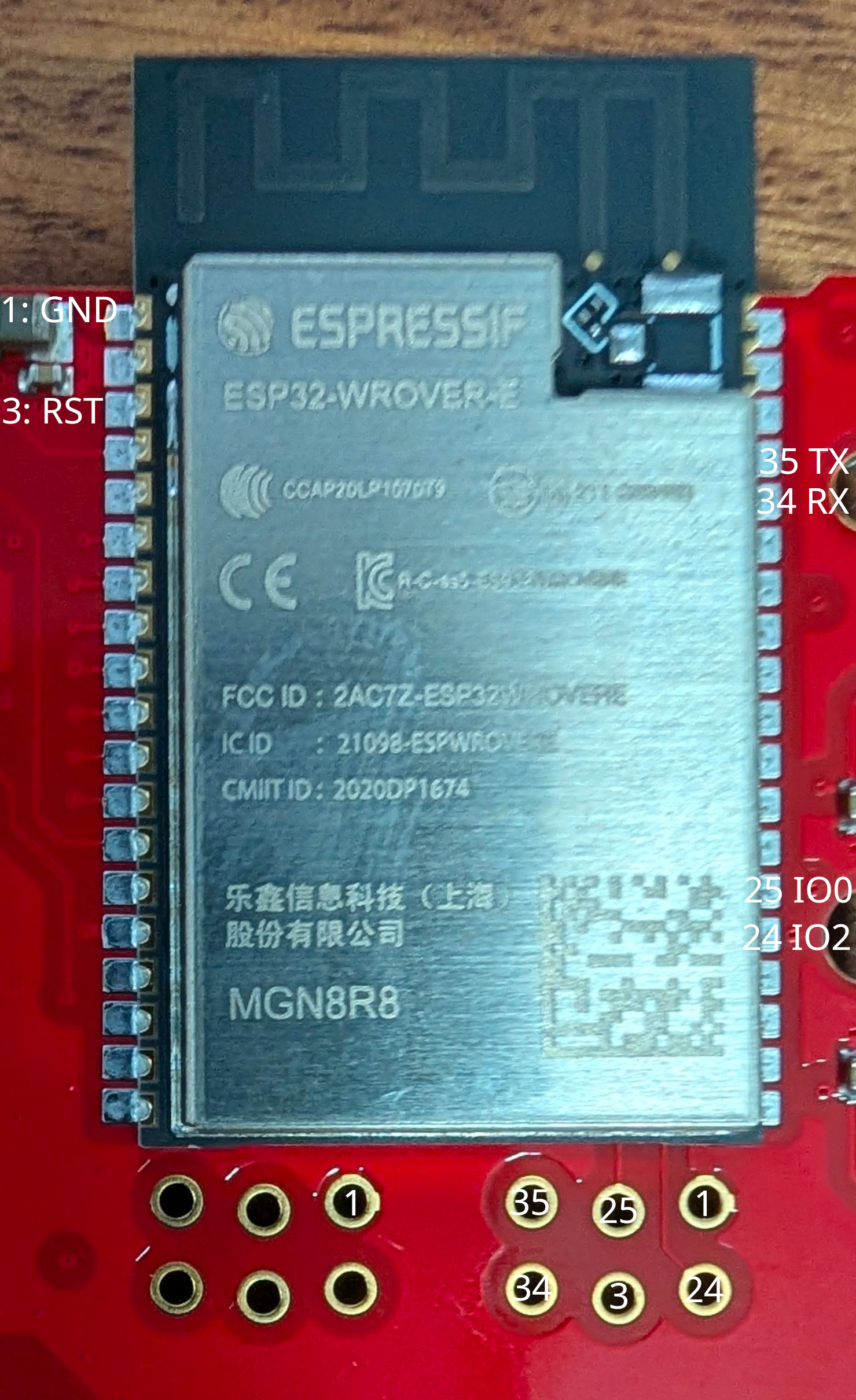 Figure 1: FireBoard 2 internal ESP32-WROVER-E (MGN8R8) module and unpopulated 6-pin 1.27mm UART bootloader header with verified pin numbers.
2.2 Unpopulated 6-Pin 1.27mm (0.050") Debug Header Pinout
Located immediately below the ESP32-WROVER-E module on the main PCB. All pads were verified by continuity against the castellated ESP32-WROVER-E pins:
      TOP ROW (Closer to ESP32 bottom edge)
   +----------------+----------------+----------------+
   |  [Pin 35] *    |  [Pin 25]      |  [GND]         |
   |  UART0 TXD0    |  GPIO0 (BOOT)  |  Ground        |
   |  (Right #23)   |  (Right #14)   |  (Shield/1/15) |
   +----------------+----------------+----------------+
   |  [Pin 34]      |  [Pin 3]       |  [Pin 24]      |
   |  UART0 RXD0    |  EN / RST      |  GPIO2 (Strap) |
   |  (Right #22)   |  (Left #3)     |  (Right #13)   |
   +----------------+----------------+----------------+
      BOTTOM ROW (Closer to PCB edge)

   * [Pin 35: TXD0] (top-left pad) outputs 3.30V when FireBoard is ON
     and 0.00V when FireBoard is OFF — wire this pad to MOSFET Pin 1 (Gate).
| Header Pad | ESP32 Module Pin | Function | Voltage (FireBoard ON) | Voltage (FireBoard OFF) | Notes |
|---|---|---|---|---|---|
[35 TXD0] |
Pin 35 (Right #23) |
GPIO1 / U0TXD |
$3.30\text{ V}$ (Idle High) | $0.00\text{ V}$ | Used as the $3.3\text{ V}$ ON/OFF trigger for MOSFET Pin 1 (Gate) |
[34 RXD0] |
Pin 34 (Right #22) |
GPIO3 / U0RXD |
$3.30\text{ V}$ | $0.00\text{ V}$ | UART0 receive input |
[25 IO0] |
Pin 25 (Right #14) |
GPIO0 (Boot Strap) |
$3.30\text{ V}$ | $0.00\text{ V}$ | Hold at $0\text{ V}$ (GND) while pulsing [3 RST] to enter UART Download Mode |
[3 RST] |
Pin 3 (Left #3) |
CHIP_PU (EN / RST) |
$3.30\text{ V}$ | $0.00\text{ V}$ | Active-low hardware reset ($0\text{ V}$ resets ESP32) |
[24 IO2] |
Pin 24 (Right #13) |
GPIO2 (Boot Strap) |
$0.00\text{ V}$ | $0.00\text{ V}$ | Must be low/floating to enter serial bootloader |
[GND] |
Pins 1, 15, 38, 39 | Common Ground | $0.00\text{ V}$ | $0.00\text{ V}$ | Connected to ESP32 RF shield can and battery negative (-) |
Additional Module Reference Pad: Left #2 (Pin 2: 3V3) carries the regulated $3.30\text{ V}$ rail when the FireBoard is powered on and drops to $0.00\text{ V}$ when powered off.
2.3 Hardware & Network Identity Reference
| Device / Component | Property | Value | Notes |
|---|---|---|---|
| XIAO ESP32-C3 Bridge | Hostname (FQDN) |
fireboardctl.drheck.dev (fireboardctl) |
Only device on Wi-Fi; resolved in Unbound on danknasty |
| XIAO ESP32-C3 Bridge | Static DHCP IPv4 | 10.0.0.71 |
Reserved in /etc/dhcpd.conf (~/git/router_config/dhcpd.conf) on danknasty |
| XIAO ESP32-C3 Bridge | Wi-Fi STA MAC | 80:f1:b2:51:49:20 |
Seeed Studio XIAO ESP32-C3 2.4 GHz Wi-Fi interface |
| FireBoard 2 Unit | Device ID / Serial | FBX2-GJ8RC3JRD |
FireBoard 2 6-Channel Thermometer (ESP32-WROVER-E / ESP32-D0WD-V3 rev v3.1) |
| FireBoard 2 Unit | Bluetooth LE MAC (Base + 2) |
94:54:c5:f7:1c:fa |
Active whenever the FireBoard 2 is powered on |
| FireBoard 2 Unit | Wi-Fi STA MAC (Base) |
94:54:c5:f7:1c:f8 (Unconfigured / No IP) |
FireBoard 2 is not connected to Wi-Fi and holds no IP address |
| FireBoard 2 Unit | Battery Pack | 1S Li-Ion Pouch Cell ($3.7\text{ V}$ nominal, $4.20\text{ V}$ full) |
Powers both the FireBoard 2 and the IRLB8721PBF MOSFET-switched XIAO ESP32-C3 |
2.4 Why the Stock FireBoard Firmware Is Bypassed via BLE
- Closed Local Network Surface: Full 65,535-port TCP/UDP
nmapscans and packet captures confirmed the stock FireBoard 2 firmware listens on zero local ports and requires remote cloud servers when on Wi-Fi. Keeping the FireBoard 2 off Wi-Fi and reading its local BLE GATT server eliminates all external network traffic. - Locked Factory Silicon (
eFuses): Interrogation over the 6-pin UART bootloader header proved all hardware security eFuses on the FireBoard's internalESP32-WROVER-Eare permanently burned:- Flash Encryption (
FLASH_CRYPT_CNT = 127/0b1111111): All 7 bits burned and write-protected; plaintext flashing renders the chip unbootable. - UART Crypto Disabled (
DISABLE_DL_ENCRYPT = True,DISABLE_DL_DECRYPT = True): The ROM bootloader is physically barred from encrypting new images or decrypting flash over UART. - Secure Boot v1 (
ABS_DONE_0 = True): Only images signed with FireBoard's private key (BLOCK2, read/write protected) are booted. - Silent UART Console (
MTDOStrapped Low +ESP_LOG_NONE): Zero application log bytes are emitted onUART0during normal boot.
- Flash Encryption (
Click to expand full ESP32-D0WD-V3 Security eFuse Register Dump (espefuse summary)
FLASH_CRYPT_CNT        (BLOCK0) = 127 R/- (0b1111111)  [Flash encryption permanently enabled; odd bit count = 7; Write-Protected]
FLASH_CRYPT_CONFIG     (BLOCK0) = 15  R/W (0xf)        [Full AES flash encryption tweak configuration]
ABS_DONE_0             (BLOCK0) = True R/W             [Secure Boot V1 permanently enforced on boot]
DISABLE_DL_ENCRYPT     (BLOCK0) = True R/W             [UART bootloader flash encryption disabled]
DISABLE_DL_DECRYPT     (BLOCK0) = True R/W             [UART bootloader flash decryption disabled]
DISABLE_DL_CACHE       (BLOCK0) = True R/W             [UART bootloader MMU flash cache disabled]
JTAG_DISABLE           (BLOCK0) = True R/W             [Hardware JTAG debugging permanently disabled]
CONSOLE_DEBUG_DISABLE  (BLOCK0) = True R/W             [ROM BASIC fallback console disabled]
BLOCK1 (Flash Key)              = ?? ?? ... -/-        [256-bit AES Flash Encryption Key: Read & Write Protected]
BLOCK2 (Secure Boot Key)        = ?? ?? ... -/-        [256-bit Secure Boot Key: Read & Write Protected]
3. FireBoard 2 BLE GATT Protocol Reference
Zero Cloud Dependency: The FireBoard 2 BLE GATT server remains active with zero Wi-Fi configuration, allowing the XIAO ESP32-C3 (fireboardctl.drheck.dev) to stream all 6 channels locally.
| GATT Attribute | UUID / Value | Properties | Description |
|---|---|---|---|
FIREBOARD_DATA_CHAR_UUID |
c2f780ec-45e1-452b-a879-327e3140d1f1 |
Notify |
Streams UTF-8 JSON temperature packets every 3–5s per active probe channel |
FIREBOARD_CONTROL_CHAR_UUID |
c2f780ec-45e1-452b-a879-327e3140d1e8 |
Write |
Writing single byte 0x01 starts the notification stream on d1f1 |
FIREBOARD_START_STREAM_BYTE |
0x01 (b'\x01') |
1 Byte |
Must be written after enabling notifications (CCCD) on d1f1 |
BLE Handshake & Notification Payload Format
- Scan & Connect: Connect to BLE MAC
94:54:c5:f7:1c:fa(or any device matching prefix94:54:c5:f7:1c:/ nameFBX). No pairing PIN or bond is required. - Subscribe: Enable GATT notifications on
c2f780ec-45e1-452b-a879-327e3140d1f1. - Start Stream: Write
0x01(1 byte, with response) toc2f780ec-45e1-452b-a879-327e3140d1e8. - Parse JSON Notifications: The FireBoard immediately begins emitting UTF-8 JSON notifications for each connected thermistor probe (
channel1through6):{ "channel": 1, "temp": 225.4, "degreetype": 2, "date": "2026-09-28T20:30:00Z" }channel: Probe port number (1..6).temp: Floating-point temperature (nullor<= 0when unplugged).degreetype:2= Fahrenheit (°F),1= Celsius (°C).
4. Firmware Repository (~/git/grill-sync) & Magic Constants (include/config.h)
All hardware, BLE protocol, ADC resistor, and network constants are isolated in include/config.h (with Wi-Fi credentials in gitignored include/secrets.h).
Repository Layout
platformio.ini— PlatformIO configuration targetingseeed_xiao_esp32c3(huge_app.csv3.1 MB partition table,NimBLE-Arduino,ArduinoJson).include/config.h— Central configuration file containing all network URLs, bridge identity (fireboardctl.drheck.dev,10.0.0.71,80:f1:b2:51:49:20), and BLE GATTUUIDs, start byte (0x01), resistor divider values, and voltage thresholds.UUIDs.include/secrets.example.h/include/secrets.h— Local Wi-Fi credentials (WIFI_SSID,WIFI_PASSWORD) and optional local overrides.src/main.cpp— Non-blocking BLE GATT client, JSON parser,battery monitor,and HTTP POST transmitter.
Complete Reference of Constants in include/config.h
| Constant | Default Value | Purpose & When to Change |
|---|---|---|
BRIDGE_DHCP_HOSTNAME |
"fireboardctl" |
DHCP client hostname announced by the XIAO ESP32-C3. |
BRIDGE_FQDN |
"fireboardctl.drheck.dev" |
Local DNS name in Unbound (10.0.0.71). |
BRIDGE_WIFI_MAC |
"80:f1:b2:51:49:20" |
Wi-Fi STA MAC of the Seeed Studio XIAO ESP32-C3 reserved as 10.0.0.71 in /etc/dhcpd.conf on danknasty. |
BRIDGE_STATIC_IPV4 |
"10.0.0.71" |
Static DHCP IPv4 address assigned to fireboardctl.drheck.dev. |
INGEST_URL |
"http://10.0.0.3:8088/api/ingest" |
Target HTTP POST URL on host ul (10.0.0.3 ports 8088 and 8000). |
HTTP_POST_INTERVAL_MS |
5000UL (5s) |
How frequently the XIAO posts temperature snapshots to ul when BLE is connected. |
HTTP_HEARTBEAT_INTERVAL_MS |
15000UL (15s) |
How frequently the XIAO posts status heartbeats when scanning for BLE. |
WIFI_CONNECT_TIMEOUT_MS |
10000UL (10s) |
Maximum time spent waiting for Wi-Fi association per attempt. |
FIREBOARD_DEVICE_ID |
"FBX2-GJ8RC3JRD" |
Device ID reported in JSON payloads to ul. |
FIREBOARD_BLE_MAC |
"94:54:c5:f7:1c:fa" |
Bluetooth LE MAC of the FireBoard 2 (Base MAC + 2). Change if pairing with a replacement FireBoard unit. |
FIREBOARD_MAC_PREFIX |
"94:54:c5:f7:1c:" |
OUI/prefix matched during BLE scanning. |
FIREBOARD_LOCK_TO_MAC |
0 |
Set to 1 to only connect to FIREBOARD_BLE_MAC, or 0 to also connect to any nearby device advertising "FBX" / "FireBoard". |
FIREBOARD_DATA_CHAR_UUID |
"c2f780ec-45e1-452b-a879-327e3140d1f1" |
FireBoard 2 BLE GATT Notify characteristic that outputs JSON temperature readings. |
FIREBOARD_CONTROL_CHAR_UUID |
"c2f780ec-45e1-452b-a879-327e3140d1e8" |
FireBoard 2 BLE GATT Write characteristic that starts the stream when 0x01 is written. |
FIREBOARD_START_STREAM_BYTE |
0x01 |
Magic wake byte written to FIREBOARD_CONTROL_CHAR_UUID upon BLE connect. |
FIREBOARD_MAX_CHANNELS |
6 |
Maximum probe channel index (Channels 1..6). |
FIREBOARD_PROBE_STALE_MS |
30000UL (30s) |
Time without a BLE notification before a channel is considered unplugged. |
ENABLE_BATTERY_ADC012x 100kΩA0GPIO20A0PIN_BATTERY_ADCA0GPIO2VOLTAGE_DIVIDER_R1_OHMS100000.0fBAT+A0VOLTAGE_DIVIDER_R2_OHMS100000.0fA0GNDADC_CALIBRATION_FACTOR1.000fBATTERY_FULL_VOLTS4.15f100%BATTERY_EMPTY_VOLTS3.30f0%BATTERY_LOW_CUTOFF_VOLTS3.25fENABLE_BATTERY_ADC15. Dashboard Infrastructure Reference on Host ul (https://grill.drheck.dev)
| Component | Path / Address | Details |
|---|---|---|
| Public URL (SSO Protected) | https://grill.drheck.dev (https://fireboard.drheck.dev) | Protected by Authentik ForwardAuth (Grill Monitor (FireBoard 2) application tile in user portal) |
| BLE-to-Wi-Fi Bridge Host | fireboardctl.drheck.dev (10.0.0.71 • MAC 80:f1:b2:51:49:20) |
Seeed Studio XIAO ESP32-C3; static DHCP lease in /etc/dhcpd.conf and local DNS in /var/unbound/etc/unbound.conf on danknasty |
| Unauthenticated Ingest API | http://10.0.0.3:8088/api/ingest / http://10.0.0.3:8000/api/ingest / https://grill.drheck.dev/api/ingest |
Accepts POST JSON ({"device_id": "FBX2-GJ8RC3JRD",) |
| Docker Compose & App Source | /data/docker/grill/docker-compose.yml, /data/docker/grill/app.py, /data/docker/grill/static/index.html |
Docker container grill running FastAPI + SQLite + Chart.js live/historical multi-channel dashboard (100% local, zero cloud functionality) |
| Persistent SQLite Database | /data/docker/grill/data/grill.db |
Stores historical temperature series (15m, 1h, 3h, 6h, 12h, 24h views) and bridge ping RTT history |
| Dedicated Docker ULA IPv6 | fd77:7777:5010:0:1337:f1ac:d00d:fb02 (Port 8000) |
Bound on eth77 (10.0.0.3:8088 and 10.0.0.3:8000 mapped on IPv4 LAN for fireboardctl.drheck.dev) |
| DNS Configuration | ~/git/router_config/unbound.conf & update_dns.py |
Local Unbound (10.0.0.100 / fd77:7777:5010::1337:f1ac:d00d:aaaa) on danknasty + public deSEC IPv6 GUA sync |
| Nginx Site Config | /etc/nginx/sites-available/grill |
Proxies / with Authentik ForwardAuth and /api/ingest with auth_request off |
| Backup & Restore Scripts | ~/git/backups/ul/scripts/grill_backup, grill_restore |
shellcheck-verified backups with par2 create -r10 parity archives in /data/backups/services/grill/ |